Basics
Contents
- Basics
Introduction
This page contains basic concepts for users working with SOZ-LIVE.
More technical information on the use of SOZ-LIVE is included in the Technical Information document.
Commands
You can interact with the program in a number of ways.
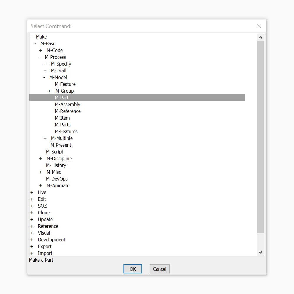
The easiest way to interact with SOZ is to type Y on the command line - a dialog box appears with a tree-view of options to select from.
The full list of of commands are here.
Note
All SOZ commands are in the same format, eg M-*, S-*, E-*, U-*, etc, so as not to interfere with conventional CAD shortcuts.
Once you know the name of a command, you can type that command instead.
Y was chosen as it is the only single key not used as a standard CAD command shortcut.
Dialog Boxes
The Graphical User Interface (GUI) is the primary means of interacting with the project. There are three basic types of dialog boxes used in the project:
The following sections describe each of the different cases.
Making Objects
Each SOZ-LIVE Class Make (& Edit) Functions have a dialog box developed on-the-fly.
Each argument creates an entry in the dialog box to be filled in by the user.
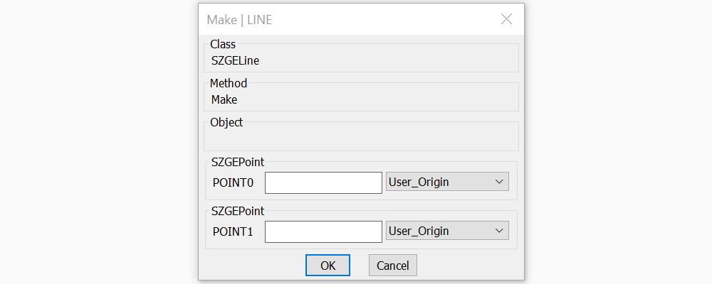
For example, the dialog for the class SZGELine has two required arguments:
- POINT0 - an atom field which is required to be of type SZGEPoint
- POINT1 - an atom field which is required to be of type SZGEPoint
Note
Only fully completed dialogs - one with valid entries for each field, will be parsed by the Make routine properly and return a valid Object.
Any class that is derived or one that interfaces with the type is also valid.
The alternative classes available for each argument are available from theUser_MakeOption.
You can Cut and Paste values from one field to another - as long as the Type of the Value / Object / Entity is compatible.
The entry is either an Atom Field or a List Field - depending upon the type of each of the arguments for the Class…
Atom Field
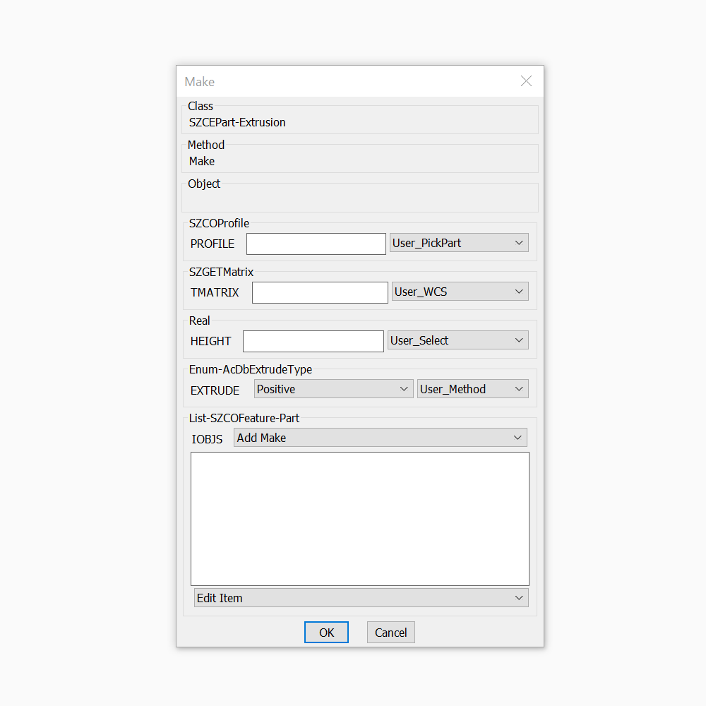
Each atom field has a number of components to it..
- the Border - that contains the name of the class that is required to be specified. eg. Real
- the Key - the name of the argument being specified. eg: HEIGHT
- the EditBox - where the value of the argument is entered / displayed
- the Options DropDown - a list of options available to specify the value for the argument.
Where the Options vary depending upon the Class being created, but include:
- Make - Which brings up a new dialog box to create an object of the specific Class
- Select - Which brings up a new dialog box to select an object of the specific Class.
- Pick - Enables the User to select an Object on the Screen
- Edit - Edits an existing object in a new dialog box.
- Command - Use the Command Line version for creating the object.
Note
All options are prefixed with User_ to indicate that they are user methods - selectable by the User.
List Field
Each list field has five components to it..
- the Border - that contains the name of the class that is required to be specified.
- the Key - the name of the argument being specified. eg: IOBJS
- the Make Options Dropdown - at the top of the ListBox.
- the ListBox - where the values of the argument is displayed - double clicking on a entry will Edit the value.
- the Edit Options DropDown - a list of options available to Edit the list.
Where Make Options include:
- Make - Which brings up a new dialog box to create an object of the specific Class.
- Select - Which brings up a new dialog box to select an object of the specific Class.
- Pick - Enables the User to select an Object on the Screen.
- PickSet - Enables the User to select a set of Objects on the Screen.
- PickList - Enables the User to pick a List of Objects on the Screen.
And Edit Options include:
- Delete the List
- Move Item to first / last / up / down.
- Reverse the list
- Remove an item
- Edit an item
- Clone an Item
Note
Double clicking on an Item Edits the Item.
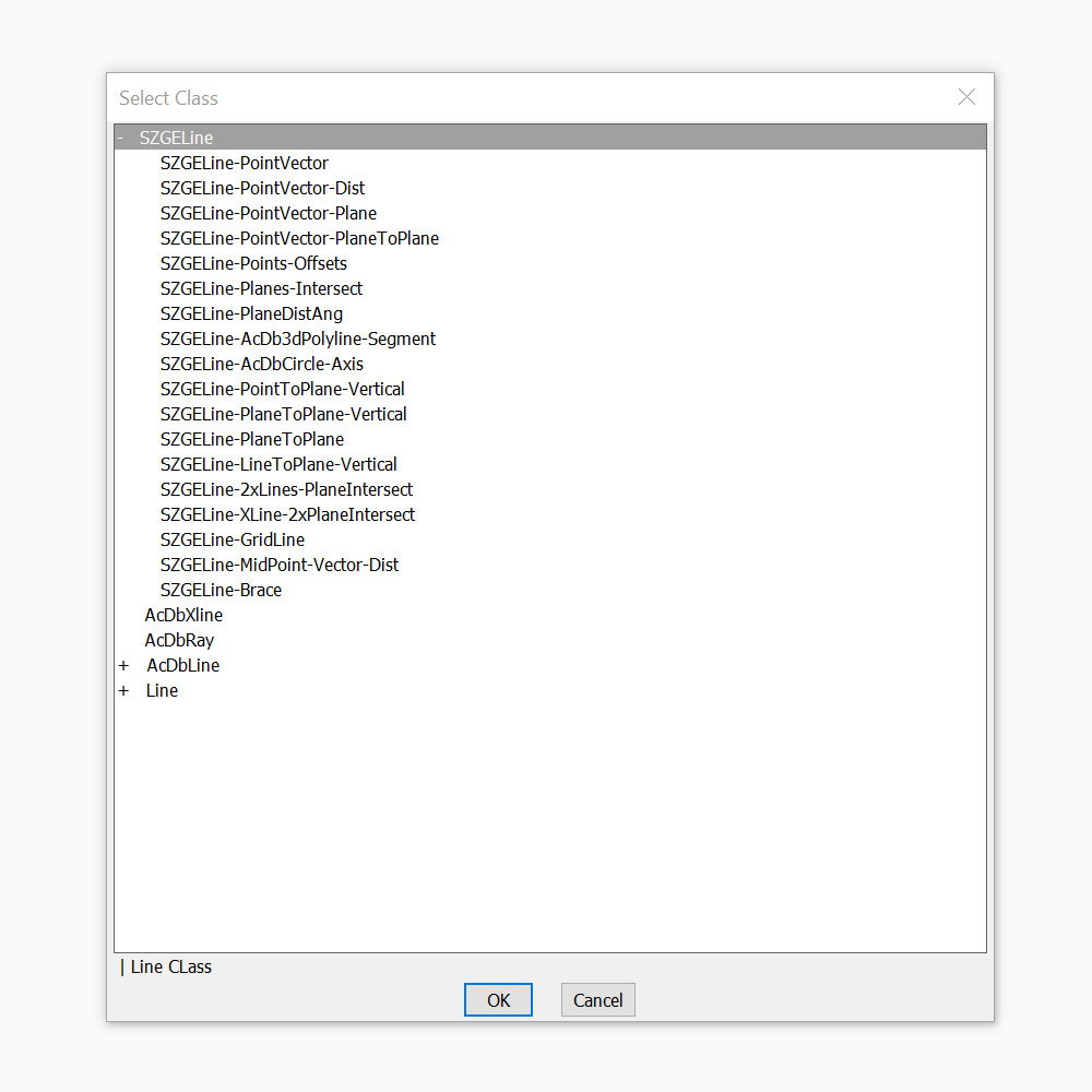
Class Selection
The class selection dialog is a Tree-view showing the various options of Classes for the user to select.
Object Selection
The object selection dialog is a basic list of suitable available objects for the user to select.
Sequence
The Dialog Box sequence to crate a Line Entity would follow the following sequence, with the User_Make option chosen at each stage.
LIVE
LIVE is a Node-Based UI for SOZ that enables the user to create visual scripts for iterative design.
The routines are built into the Core of SOZ, and consist of under 1000 lines of code.
Functionality includes:
- Adding Nodes,
- Adding Links between the Nodes
- Editing Nodes
- Updating Nodes and Entities.
- Deleting Nodes and Links
LIVE objects are created in PaperSpace while the modelling entities are created in ModelSpace.
The three Object Types for LIVE are:
LIVE Nodes
A Node is the graphical object that represents data that can be edited and updated to visualise alternative designs.
In LIVE, a Node is a BlockReference Entity, an instance of a Block Object that represents the Function / Method being visualised.
In SOZ-LIVE any Method, including all Make methods for Classes can be used as Nodes, thereby giving the greatest flexibility to the system possible.
Every Method has 0 or more inputs and a Return value. These are shown as Attributes within the Node.
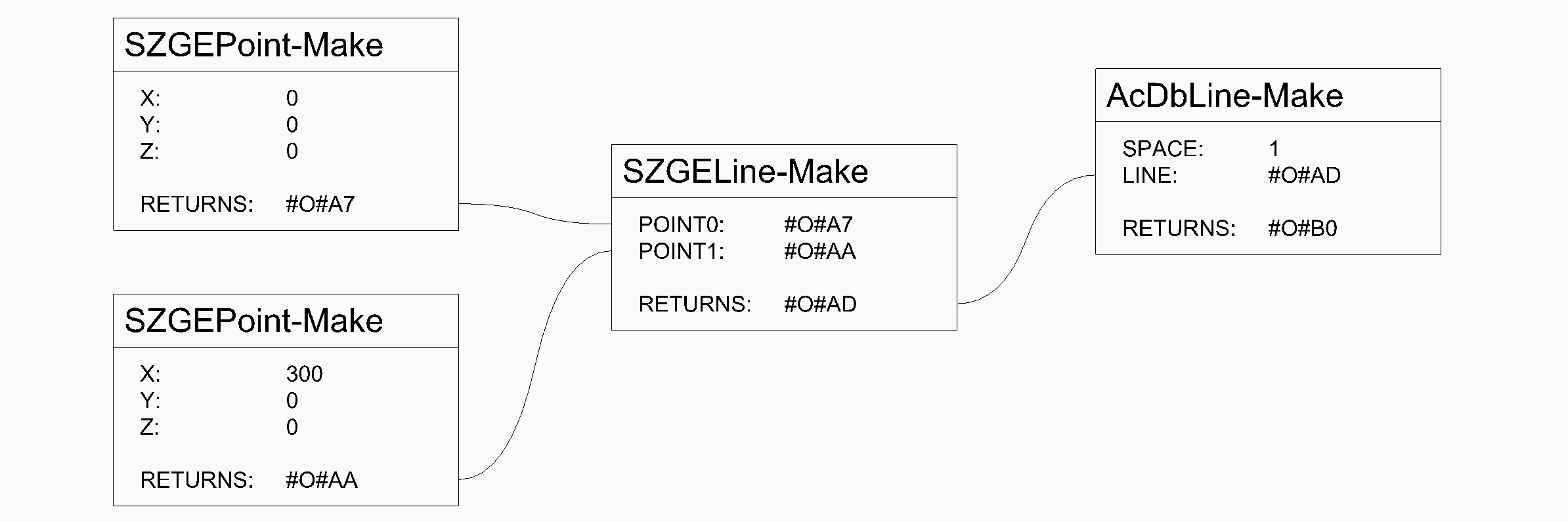
LIVE Links
A Link is the graphical object that represents the flow of data from one Node to another. (Typically Left to Right.)
Each Link will update when the corresponding Node is moved or edited.
LIVE Points
A Point is the graphical object that enables picking of data Values within a Node.
Each Point will update when the corresponding Node is moved or edited.
Drawing Process
The basic SOZ-LIVE process for drawing develoment follows four phases:
During each phase the basic approach to using SOZ is followed:
- Make objects & entities
- using the Y command or M-* commands listed here.
- Edit objects & entities
- using the E-* commands.
- which then Updates the model.
Note
The process of drawing develoment doesn’t have to be linear (moving from Specify to Draft to Model etc.)
SOZ enables most entities to be created from within the Dialog Boxes as required.
This means that a non-linear approach to model creation can be achieved.
And because changes can be made, editing can be done later.
Specify
The Objects and Values that form the basis for the Entities are created in this phase.
These include:
- Numbers
- Equations
- Calculations
- Geometric Values and Objects:
- Shapes
- Profiles
- Curves
- Points
Draft
The Entities that form the basis for the Models are created in this phase:
- Points
- Planes
- Curves
- Lines
- Arcs
- Circles
- etc
- Grids
Model
Modelling Entities are created in the phase, using previously defined Entities and objects:
Part
Parts are 3dSolid Entities, made from Features.
In the drawing they exist as a BlockReference for a given Block (the Definition).
When editing the Part, the changes are make to the Definition and then the model is updated to reflect the changes.
As well as a generic Part class, there are also a number of pre-defined Part classes that can be created:
- Extrusion
- Extrusion using a Circle
- Extrusion using a Polyline.
- Sweep
- PolySoild
- Sphere
- Faces
These can then be further developed by adding features.
Features
There are a variety of types of Features that can be created. Including:
- Boolean Solids
- Union
- Intersection
- Subtraction
- Boolean Corners
- Chamfers
- Fillets
- Slicing of Solids
- Profile Cuts
- Boolean Toolbodies
- Patterned Boolean Solids
Assembly
Assemblies are made of Parts.
Present
The presentation phase using SOZ-LIVE is in development.